
Shu Guang Shu Guang

How to Choose the Right Surge Arrester?

Time:2026-09-14 Author:Isabella
0%

Choosing the right Surge Arrester is not a matter of selecting the largest model. It requires a careful match between electrical conditions, equipment sensitivity, and installation risks. A reliable choice begins with the system voltage, grounding arrangement, and expected transient environment. It also considers the arrester’s maximum continuous operating voltage, nominal discharge current, and voltage protection level.

Real installations often reveal details that product tables cannot show. A rooftop solar system may face repeated lightning impulses, while a factory control cabinet may suffer frequent switching surges. Long cable runs can increase residual voltage at the protected equipment. Poor bonding can weaken an otherwise capable protection system. Small details matter.

Check the labels closely.

Professional selection should follow recognized technical guidance, including IEC 61643-11 where applicable, while considering local electrical requirements. Type 1, Type 2, and Type 3 devices serve different positions within a protection concept. Their coordination must be verified, rather than assumed from appearance or brand reputation. Backup protection, conductor length, enclosure conditions, and maintenance access also deserve attention.

There is no perfect arrester for every site. A device with a high discharge rating may still provide inadequate protection if its voltage level is unsuitable. Conversely, an economical model may perform well in a controlled environment. Product claims can sound convincing, but field measurements, manufacturer documentation, and qualified engineering review remain important. This guide examines those practical factors, including common selection mistakes that are easy to overlook.
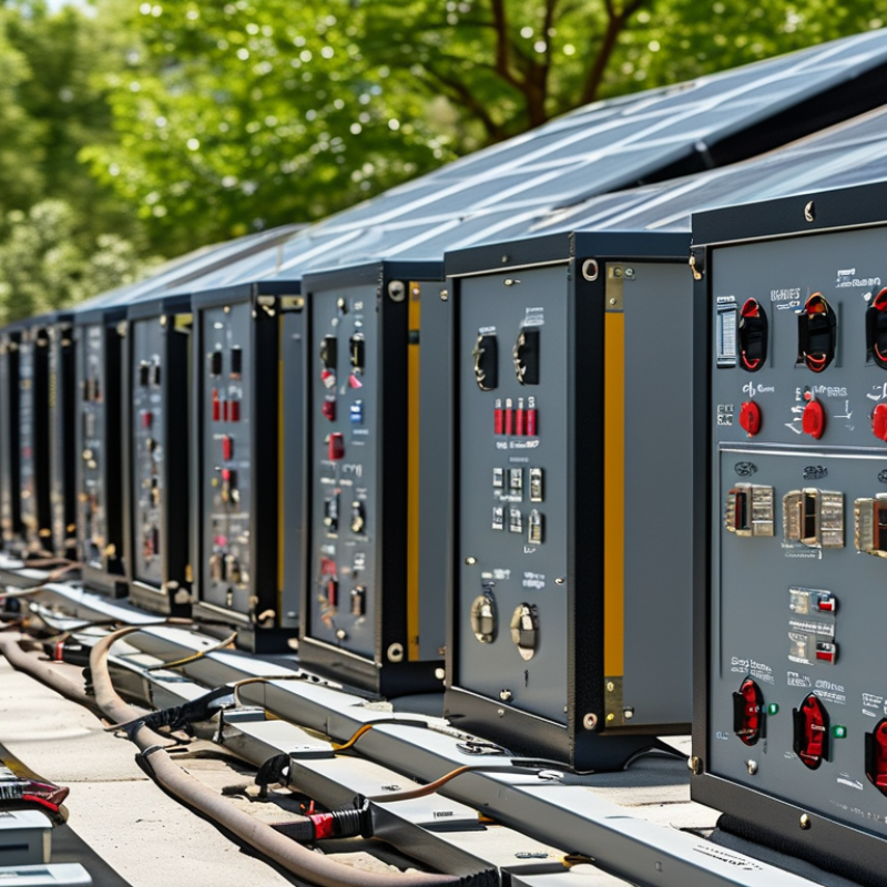
How to Choose the Right Surge Arrester?

Understand the Purpose and Protection Needs of Surge Arresters

How to Choose the Right Surge Arrester?

Understand the Purpose and Protection Needs of Surge Arresters

A surge arrester limits short, high-voltage spikes caused by lightning or switching events. It directs excess energy safely toward the grounding system. It does not correct continuous overvoltage or poor wiring. That distinction matters.

Choose an arrester according to the system voltage, grounding method, expected surge exposure, and equipment sensitivity. Check its maximum continuous operating voltage and nominal discharge current. A device with inadequate ratings may fail during a severe event. In field inspections, loose grounding connections often weaken otherwise suitable protection. Installation location also matters. A main service entrance needs different coordination from a control panel beside a motor. Keep connecting leads short and straight. Long bends increase residual voltage. That detail is easy to overlook.

Tips: Match the arrester with upstream protection and the equipment’s impulse withstand level. Inspect terminals for heat marks, corrosion, or mechanical looseness. Replace damaged units promptly. If the building has rooftop equipment or overhead lines, reassess the risk after renovations. A previous selection may no longer fit. Do not rely on labels alone; review test data and installation conditions. When uncertain, consult a qualified electrical professional who can verify system measurements, grounding continuity, and coordination.

Identify System Voltage, Grounding, and Installation Conditions

How to Choose the Right Surge Arrester?

Start with the system voltage, not the equipment label. Confirm the nominal line-to-line voltage, frequency, and the maximum continuous operating voltage. For a 400 V grounded wye system, line-to-ground stress differs from a 400 V ungrounded delta system. Select the arrester’s MCOV above the highest normal voltage, while checking temporary overvoltage conditions. The IEC 60099-4 framework emphasizes these electrical ratings for metal-oxide arresters. Do not guess. A small voltage mismatch can cause premature thermal failure.

Grounding changes the protection duty. Verify whether the neutral is solidly grounded, resistance grounded, impedance grounded, or isolated. Measure the actual grounding path, including bonding conductors and earth connections. IEEE guidance treats grounding and coordination as essential parts of surge protection, not optional accessories. The U.S. Energy Information Administration’s 2023 Electric Power Annual reported roughly 5.5 hours of average interruption duration, including major events. Surges often arrive during those unstable moments.

Installation conditions deserve equal attention. Record cable length, altitude, humidity, pollution, available fault current, and lightning exposure. Keep connections short and straight; long bends add inductive voltage during fast impulses. Check backup protection, thermal disconnection, enclosure rating, and coordination between upstream and downstream arresters. Field reality disagrees with many drawings. A well-rated device can still underperform when installed far from the load or bonded to a weak grounding point. Recheck the site after commissioning.

How to Choose the Right Surge Arrester?

Identify the system voltage, grounding arrangement, and installation conditions before selecting the arrester.

System Voltage

Confirm the nominal line-to-line and line-to-earth voltages. The arrester's continuous operating voltage must not be lower than the expected steady-state voltage.

Grounding Arrangement

The values shown are representative minimum Uc values for solidly grounded TN systems, calculated as 1.10 × phase-to-earth voltage. Ungrounded and IT systems require a separate evaluation.

Installation Conditions

Check lightning exposure, expected surge current, backup protection, conductor length, enclosure location, and the required voltage protection level.

Reference values are based on common low-voltage AC system configurations. Final arrester selection should be verified against the applicable installation standard and site conditions.

Compare Surge Arrester Types and Essential Technical Ratings

Choosing the right surge arrester starts with comparing its protection role, not its advertised discharge current. Type 1 arresters handle high-energy lightning currents at the service entrance. Type 2 devices protect distribution panels from residual and switching surges. Type 3 units sit close to sensitive equipment, such as control screens or laboratory instruments. Some installations need coordinated Type 1 and Type 2 protection.

Technical ratings reveal whether the device fits the electrical system. Uc, or maximum continuous operating voltage, must exceed the system’s normal voltage. Up, the voltage protection level, shows how much voltage equipment may still experience during a surge.

In indicates nominal discharge current, while Imax represents the higher discharge current the arrester can withstand. For lightning-current applications, Iimp and its 10/350 μs waveform deserve careful attention.

A higher kA rating alone does not guarantee better protection. I have seen installations with powerful arresters but poor earthing and long connecting wires. The result was disappointing. Keep conductors short, straight, and properly bonded. Check the system voltage, grounding arrangement, short-circuit rating, and backup protection. AC and DC circuits also require different arrester designs. Coordination matters. A downstream arrester with a lower Up rating may protect electronics better, but only when upstream devices share the surge energy correctly. Manufacturer test data, installation instructions, and applicable electrical standards should guide the final selection. No rating tells the whole story.

Assess Energy Capacity, Standards, and Environmental Durability

How to Choose the Right Surge Arrester?

Energy capacity deserves more attention than a single kA figure. A 20 kA rating does not automatically provide twice the protection of 10 kA. The waveform, discharge duration, clamping voltage, and repeated surge exposure also matter. IEEE C62.41.2 identifies the 6 kV/3 kA combination wave as a common benchmark for low-voltage equipment testing. Compare this test condition with the installation’s measured risk, not just the headline rating. I would not trust an arrester selected from one number alone.

Standards provide a more reliable comparison. IEC 61643-11 defines performance and test requirements for low-voltage surge protective devices. UL 1449 evaluates key safety and protective characteristics in applicable installations. Check the declared maximum continuous operating voltage, nominal discharge current, voltage protection level, and thermal behavior. The wrong operating voltage can cause premature failure. Small detail, serious consequence.

Environmental durability can decide service life. NOAA climatology estimates about 25 million lightning flashes occur across the United States each year, exposing many systems to repeated transient stress. Review temperature limits, humidity testing, UV exposure, salt mist, altitude, and enclosure protection. IEC 60068 environmental test methods can help interpret these claims. Outdoor equipment near coastlines needs different protection from equipment inside a dry control room. Some datasheets remain vague here. Ask for test conditions, duration, and failure criteria before purchasing.

Plan Proper Installation, Coordination, and Long-Term Maintenance

How to Choose the Right Surge Arrester?

Proper installation, coordination, and maintenance determine whether a surge arrester protects equipment or becomes a hidden failure point. IEC 60099-5 identifies moisture, contamination, and thermal ageing as major service concerns. The IEEE surge protection guide also stresses short, straight connection leads. Long bends increase residual voltage during a fast transient.

Select the arrester’s continuous operating voltage above the system’s maximum sustained voltage. Then verify discharge current, energy capability, grounding, and insulation coordination. Coordination matters. A service entrance arrester should handle larger energy, while downstream devices manage sensitive equipment. CIGRE technical publications report that repeated temporary overvoltages can accelerate arrester ageing, even without visible damage. That is easy to miss. I have seen installations with correct ratings but poor cable routing.

Tips: Keep phase and ground leads short. Use a visual status indicator. Record installation dates, measured leakage current, and major surge events. Inspect after lightning, switching faults, flooding, or unusual heating. NFPA research has repeatedly linked electrical distribution equipment with a significant share of building fires, so loose terminals and failed protective devices deserve prompt attention. Do not rely on appearance alone. Infrared checks, insulation testing, and leakage-current trends provide stronger evidence. Maintenance intervals should reflect pollution, humidity, lightning exposure, and load conditions. A fixed annual schedule may be convenient, but it is not always sufficient.

How to Choose the Right Surge Arrester? - Plan Proper Installation, Coordination, and Long-Term Maintenance
Selection or Planning Dimension Recommended Data to Confirm Practical Guidance Typical Reference or Acceptance Point
Electrical System Voltage Nominal line-to-line voltage and maximum continuous operating voltage Select an arrester with a continuous operating voltage (Uc or MCOV) suitable for the actual system voltage and grounding arrangement. Do not select only by nominal voltage. Uc must not be lower than the maximum sustained voltage that can occur at the installation point.
System Grounding Arrangement Solidly grounded, resistance grounded, impedance grounded, or ungrounded system Grounding affects the temporary overvoltage seen by an arrester during a single-line-to-ground fault. Verify the arrester rating against the expected fault duration and voltage rise. Use the applicable system-fault study and arrester temporary overvoltage capability.
Arrester Class and Location Service entrance, main distribution board, subdistribution board, or equipment terminal Use coordinated protection stages: a higher-energy device at the service entrance and suitable downstream protection close to sensitive equipment. Protection zones should progress from high surge-current capability upstream to lower residual voltage downstream.
Nominal Discharge Current 8/20 μs nominal discharge current, commonly 5 kA, 10 kA, or 20 kA for low-voltage applications Choose the rating according to the installation exposure, expected lightning environment, service location, and applicable product standard. Higher nominal discharge current generally provides greater surge-current duty capability, but does not by itself guarantee the lowest protection voltage.
Maximum Discharge Current Imax rating under the applicable test waveform Consider Imax where the installation is exposed to direct or nearby lightning effects, long outdoor feeders, overhead lines, or a high lightning density. Confirm the selected value against the site risk assessment and the required test classification.
Voltage Protection Level Up or residual voltage at the equipment connection point The arrester protection level should be compatible with the impulse withstand capability of the equipment. Lower Up is generally preferable when adequate energy capability is maintained. Up should be below the equipment’s rated impulse withstand voltage, including installation and coordination margins.
Lightning and Surge Exposure Lightning density, overhead conductors, cable length, switching loads, and nearby transformers Assess both lightning-origin and switching-origin transients. Motors, capacitor banks, variable-frequency drives, and transformers can generate significant switching surges. Use a documented risk assessment rather than relying only on regional lightning frequency.
Installation Wiring Length Total conductor length from the arrester to the protected equipment and earth reference Keep line and protective-earth conductors short, straight, and closely routed. Excessive conductor length increases inductive voltage during a fast transient. For low-voltage surge protection, a commonly applied design target is approximately 0.5 m or less of total connecting lead length where practicable.
Protective Device Coordination Upstream fuse or circuit-breaker type, rating, and short-circuit capability Verify the arrester’s required backup overcurrent protection and ensure that the upstream device will clear an arrester failure without reducing required service safety. Follow the arrester manufacturer’s tested backup-protection limits and the installation code.
Grounding and Bonding Protective-earth conductor, equipotential bonding, and earth terminal condition Connect the arrester to the same low-impedance bonding system used by the protected equipment. Avoid narrow, coiled, or unnecessarily long earth conductors. Bonding conductors should be sized and installed according to the applicable electrical and lightning-protection standards.
Coordination Between Protection Stages Upstream and downstream arrester characteristics, conductor impedance, and separation distance Coordinate devices so that the upstream arrester handles high-energy surges while downstream devices limit residual voltage at sensitive loads. If the required separation distance is unavailable, use a coordinated system designed for close installation. Coordination should be confirmed using manufacturer data or validated engineering calculations.
Environmental Conditions Ambient temperature, humidity, altitude, pollution, UV exposure, and enclosure rating Check derating and enclosure requirements for outdoor, coastal, dusty, chemically exposed, or high-altitude locations. Prevent moisture ingress and condensation. Use an enclosure and environmental rating appropriate for the actual installation location.
Thermal and Failure Indication Thermal disconnect, visual status indicator, remote alarm contact, and end-of-life behavior Prefer devices with clear local status indication. Remote contacts can be integrated into building management or electrical monitoring systems where continuous supervision is required. Status indicators should be visible during routine inspection and remain accessible after installation.
Equipment Compatibility Protected equipment impulse withstand, operating voltage, frequency, and wiring configuration Confirm the arrester is suitable for single-phase or three-phase systems and for the applicable conductor arrangement, such as L-N, L-PE, and N-PE protection. Verify compatibility with the equipment insulation level and the system’s conductor-to-ground voltage.
Standards and Testing Applicable product, installation, and lightning-protection standards For low-voltage surge protective devices, IEC 61643-11 is a commonly used product standard. Installation design may also require local electrical codes and lightning-protection standards. Use current editions of the standards adopted by the project jurisdiction.
Routine Inspection Inspection interval, status indicator, terminal tightness, enclosure condition, and contamination Inspect after major storms, switching incidents, electrical faults, or known surge events, as well as during scheduled maintenance. Look for discoloration, damage, loose connections, moisture, and a changed status indicator. Inspection frequency should reflect site exposure, criticality, and the maintenance program.
Replacement Planning End-of-life indication, surge history, thermal damage, and insulation condition Replace the module or complete device when the status indicator shows failure, after confirmed severe damage, or when inspection identifies unsafe degradation. Do not reset or reuse a failed arrester. Replacement parts must match the system voltage, configuration, and approved protection characteristics.
Documentation and Records Single-line diagram, ratings, installation date, test results, inspection records, and replacement history Maintain an asset record for each protection stage. Clear documentation supports fault investigation, coordination reviews, and timely replacement. Update records whenever the electrical system, grounding arrangement, or protected load changes.
Note: Final arrester selection should be verified by a qualified electrical professional using the actual system voltage, grounding method, fault conditions, equipment withstand level, local codes, and site exposure.

FAQS

What information should I confirm before choosing a surge arrester?

Confirm nominal line-to-line voltage, frequency, and maximum continuous operating voltage. Check temporary overvoltage conditions too. Do not guess.

Why does the grounding arrangement matter?

Grounding changes the arrester’s protection duty. Identify solid, resistance, impedance, or isolated grounding. Measure bonding conductors and earth connections.

Can the same arrester suit grounded and ungrounded systems?

Not always. A 400 V grounded wye system experiences different line-to-ground stress than an ungrounded delta system. Verify the actual system design.

What does MCOV mean in practical selection?

MCOV should exceed the highest normal operating voltage. A small mismatch may cause premature thermal failure. This detail is easy to overlook.

Does a higher kA rating always mean better protection?

No. Waveform, discharge duration, clamping voltage, and repeated exposure also matter. A 20 kA rating is not automatically twice as protective.

How should installation location affect the decision?

Keep connections short and straight. Long bends add inductive voltage during fast impulses. An arrester installed far from the load may underperform.

Which site conditions should be reviewed?

Record cable length, altitude, humidity, pollution, fault current, and lightning exposure. Outdoor coastal equipment may need stronger environmental protection than a dry control room.

What safety and coordination details should I check?

Review thermal disconnection, backup protection, enclosure rating, and upstream coordination. Recheck the installation after commissioning. Drawings can mislead.

How can standards help compare different arresters?

Use applicable international performance and safety standards. Compare MCOV, nominal discharge current, voltage protection level, and thermal behavior. One headline number is insufficient.

What environmental test evidence should suppliers provide?

Ask about temperature, humidity, ultraviolet exposure, salt mist, altitude, and enclosure testing. Request test duration and failure criteria. Vague datasheets deserve caution.

Conclusion

Choosing the right Surge Arrester begins with understanding the equipment and systems that need protection. Evaluate the expected surge sources, the sensitivity of connected devices, and the consequences of electrical damage. Then confirm the system voltage, grounding method, frequency, and installation conditions, including available space, indoor or outdoor placement, pollution, moisture, temperature, and altitude. These factors help determine the suitable arrester configuration and insulation requirements.

Next, compare arrester types and key technical ratings, such as maximum continuous operating voltage, nominal discharge current, residual voltage, and short-circuit withstand capability. Select an energy capacity that matches the likely surge exposure and verify compliance with applicable safety and performance standards. Proper installation is equally important: keep connections short, provide reliable grounding, coordinate protection levels throughout the system, and follow recommended spacing. Regular inspection, testing, and timely replacement will help maintain dependable protection throughout the Surge Arrester’s service life.

Isabella

Isabella

Isabella is a dedicated marketing professional with a sharp focus on driving brand growth and engagement through strategic content creation. With an extensive background in digital marketing, she combines her passion for storytelling with her keen understanding of industry trends to deliver......